



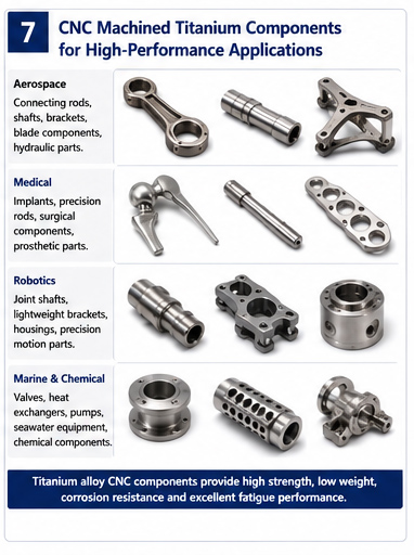
Titanium alloys are widely used in aerospace, medical devices, robotics, marine equipment, and high-performance mechanical components because of their high specific strength, excellent corrosion resistance, and favorable fatigue properties.
However, titanium alloy fatigue performance cannot be evaluated solely from tensile strength or material grade. Fatigue life is strongly affected by microstructure, surface integrity, machining condition, residual stress, environmental exposure, fretting contact, temperature, and loading conditions.
For commonly used alloys such as Ti-6Al-4V (TC4), different heat-treatment conditions and microstructures can result in significantly different fatigue behavior. Therefore, reliable titanium alloy fatigue life prediction requires a comprehensive evaluation of both material properties and manufacturing conditions.
 What Is Titanium Alloy Fatigue?
Titanium alloy fatigue refers to the progressive damage and eventual failure of a titanium alloy component under repeated or cyclic loading.
A component can experience fatigue failure even when the applied stress is significantly lower than its ultimate tensile strength. During cyclic loading, microscopic damage can accumulate until a fatigue crack forms and gradually propagates through the material.
The typical fatigue fracture process consists of three stages:
Crack Initiation → Crack Propagation → Final Fracture
1. Crack Initiation
Small cracks may originate from surface defects, machining marks, inclusions, microstructural discontinuities, or localized stress concentrations.
2. Crack Propagation
Once a crack reaches a critical size, cyclic loading causes it to propagate progressively through the material.
3. Final Fracture
When the remaining cross-sectional area can no longer support the applied load, rapid unstable fracture occurs.
For this reason, controlling the surface and microstructure of CNC machined titanium alloy parts is essential when fatigue resistance is a major design requirement.
Suggested image: Titanium alloy fatigue fracture process showing crack initiation, crack propagation, and final fracture.
 Titanium Alloy Fatigue Strength: Key Advantages
Titanium alloys offer several important advantages for fatigue-critical applications.
High Specific Strength
Titanium alloys provide an excellent strength-to-weight ratio. Their relatively low density combined with high mechanical strength makes them particularly attractive for aerospace structures and lightweight robotic components.
For a component with a defined load requirement, titanium can provide the required structural strength with lower weight than many conventional steels.
Good Fatigue Performance
Many titanium alloys exhibit good fatigue resistance when the material has an appropriate microstructure and surface condition.
Ti-6Al-4V, for example, is widely used in fatigue-critical applications because of its favorable combination of strength, toughness, corrosion resistance, and fatigue performance.
However, Ti-6Al-4V fatigue strength can vary substantially depending on heat treatment, microstructure, surface finish, stress ratio, loading frequency, and environmental conditions.
Excellent Corrosion Resistance
Titanium naturally forms a stable passive oxide film that provides excellent corrosion resistance in many environments.
Nevertheless, corrosion resistance does not mean that fatigue performance is unaffected by the service environment. Under corrosive conditions, cyclic loading and environmental exposure can interact and accelerate crack initiation or propagation.
Six Major Engineering Challenges in Titanium Alloy Fatigue
Although titanium alloys offer excellent overall mechanical performance, several factors can significantly reduce their fatigue life.
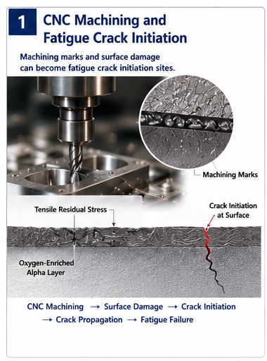
1. Surface Integrity
Surface condition is one of the most important factors affecting titanium alloy fatigue life.
Machining operations such as milling, turning, and grinding may introduce:
Tool marks
Surface roughness
Tensile residual stress
Local plastic deformation
Oxygen-enriched surface layers
Microcracks
Surface defects
These imperfections can act as preferential fatigue crack initiation sites.
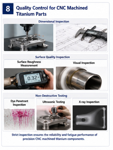
For fatigue-critical titanium components, dimensional accuracy alone is not sufficient. Engineers must also consider titanium alloy surface integrity.
Typical applications include:
Titanium alloy shafts
Titanium flanges
Aerospace connecting rods
Titanium robot joint shafts
Medical titanium components
2. Hydrogen-Induced Fatigue Damage
Titanium alloys can absorb hydrogen under certain chemical, electrochemical, and environmental conditions.
Hydrogen uptake may alter the local microstructure and, under appropriate conditions, lead to hydride formation or hydrogen embrittlement. These effects can promote crack initiation and accelerate crack propagation.
Potential risk conditions include:
Acid pickling
Certain chemical processing operations
Electrochemical environments
High-humidity or hydrogen-containing environments
Therefore, components exposed to hydrogen-producing processes should not simply use fatigue data obtained from dry-air testing.
3. Corrosion Fatigue
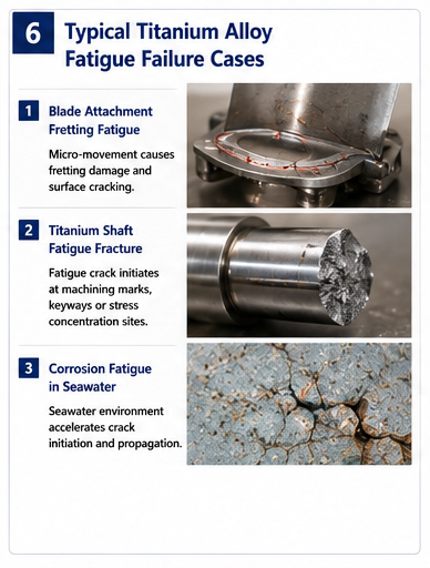
Titanium alloys have excellent corrosion resistance, but cyclic loading in aggressive environments can still produce corrosion fatigue.
In seawater or chloride-containing environments, repeated mechanical loading may interact with localized surface-film damage and crack-tip chemistry.
This creates a coupled process:
Cyclic Loading + Environmental Attack → Crack Initiation and Propagation
Applications requiring special attention include:
Desalination equipment
Marine components
Offshore oil and gas equipment
Chemical processing equipment
Titanium valve stems
Fatigue data obtained in dry air should therefore not automatically be applied to corrosive service environments.
4. Fretting Fatigue
Fretting fatigue occurs when two contacting surfaces experience small-amplitude relative motion while subjected to cyclic loading.
The resulting damage combines:
Fretting Wear + Local Stress Concentration + Fatigue Crack Initiation
Fretting fatigue is particularly important in aerospace titanium structures.
Typical locations include:
Blade dovetails
Bolt holes
Fastener interfaces
Shaft and sleeve interfaces
Contact surfaces between assembled components
Conventional S-N curves may not adequately describe the complex contact conditions associated with fretting fatigue. Component-level testing is often required for reliable engineering evaluation.
5. Microstructural Anisotropy
Titanium alloy fatigue behavior is strongly influenced by the morphology and distribution of α and β phases.
Forging and rolling processes can also introduce directional microstructures and material flow lines. As a result, fatigue properties may vary depending on specimen orientation.
Therefore:
The same titanium alloy grade does not necessarily have one universal fatigue curve.
For Ti-6Al-4V, heat-treatment condition, forging parameters, cooling rate, and sampling direction can all affect fatigue performance.
6. High-Temperature Fatigue
Titanium alloy fatigue performance changes with increasing temperature.
At elevated temperatures, factors such as:
Oxidation
Microstructural stability
Reduced material strength
Creep interaction
Grain-boundary behavior
may influence fatigue life.
For aerospace engine components and other elevated-temperature applications, room-temperature fatigue data should not be directly applied without appropriate validation.
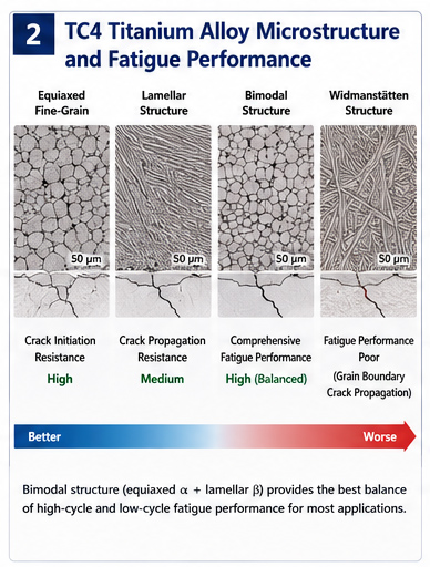
Effect of Microstructure on Titanium Alloy Fatigue Performance
Microstructure is one of the most important variables controlling the fatigue behavior of Ti-6Al-4V.
Common microstructural conditions include:
Equiaxed microstructure
Bimodal microstructure
Lamellar microstructure
Widmanstätten microstructure
Equiaxed Fine-Grain Microstructure
An equiaxed α-phase structure can provide good resistance to fatigue crack initiation and is often favorable for high-cycle fatigue applications.
Typical applications include:
High-frequency vibration components
Rotating components
Aerospace structural parts
High-cycle fatigue components
Lamellar Microstructure
Lamellar microstructures may have different crack initiation and propagation characteristics compared with equiaxed structures.
Although crack initiation can occur relatively easily under certain conditions, the lamellar morphology may provide greater resistance to subsequent crack propagation.
Therefore, lamellar microstructures should not simply be classified as universally inferior.
Bimodal Microstructure
A bimodal microstructure generally contains primary equiaxed α and transformed β regions.
It provides a useful balance between strength, ductility, crack initiation resistance, and crack propagation behavior.
For this reason, bimodal structures are widely used for demanding titanium alloy components.
Widmanstätten Microstructure
Coarse Widmanstätten structures, especially those involving unfavorable continuous grain-boundary α features, can result in inferior fatigue performance.
Careful control of forging temperature and cooling rate is therefore necessary to prevent undesirable microstructural development.
How Is Titanium Alloy Fatigue Life Calculated?
Several approaches are commonly used for titanium alloy fatigue life prediction.
The appropriate method depends on whether the component contains an initial crack, whether the loading is elastic or plastic, and whether the component is subjected to variable-amplitude loading.
1. S-N Curve Method
The S-N method, also known as the stress-life method, is commonly used for high-cycle fatigue analysis of components without a known initial crack.
A typical Basquin relationship is:
[
\sigma_a=\sigma_f'(2N_f)^b
]
Where:
(\sigma_a) = stress amplitude
(\sigma_f') = fatigue strength coefficient
(N_f) = fatigue life
(b) = fatigue strength exponent
When mean stress is present, a correction such as the Goodman relation can be applied.
For variable-amplitude loading, Miner’s linear damage accumulation rule is commonly used:
[
D=\sum\frac{n_i}{N_i}
]
where (n_i) is the number of cycles applied at a particular stress level and (N_i) is the corresponding fatigue life.
2. Paris Law for Fatigue Crack Growth
For components containing an initial crack or those designed according to a damage-tolerance philosophy, fracture mechanics methods are more appropriate.
The Paris law is commonly expressed as:
[
\frac{da}{dN}=C(\Delta K)^m
]
Where:
(a) = crack length
(N) = number of cycles
(C) = material constant
(m) = material exponent
(\Delta K) = stress intensity factor range
The crack growth life can then be estimated by integrating from the initial crack size (a_0) to the critical crack size (a_c):
[
N=\int_{a_0}^{a_c}\frac{da}{C(\Delta K)^m}
]
This approach is particularly important for aerospace structures where damage tolerance and inspection intervals are critical design considerations.
3. Manson-Coffin Method for Low-Cycle Fatigue
When a component experiences significant plastic strain, strain-life methods are generally more appropriate than a conventional S-N approach.
The plastic strain component can be described using the Manson-Coffin relationship:
\varepsilon_f'(2N_f)^c
]
The combined Coffin-Manson-Basquin relationship can then be used to account for both elastic and plastic strain components.
This method is useful for:
Low-cycle fatigue
Thermal cycling
Start-stop loading
Large-amplitude cyclic loading
Thermomechanical fatigue
Special Corrections Required for Titanium Alloy Fatigue Calculations
One of the most important considerations in titanium alloy fatigue analysis is that material handbook data cannot always be directly transferred to an actual machined component.
Four special correction factors deserve particular attention.
1. Surface Integrity Correction
Fatigue calculations should account for:
Surface roughness
Machining marks
Tensile residual stress
Oxygen-enriched surface layers
Grinding damage
Surface strengthening
For example, a polished laboratory specimen and a heavily machined production component made from the same TC4 material may have significantly different fatigue behavior.
Conversely, introducing compressive residual stress through appropriate surface treatment can improve resistance to fatigue crack initiation.
2. Microstructure Correction
Different microstructures can produce different S-N curves and fatigue crack growth behavior.
Therefore, the following should not automatically be treated as interchangeable:
Equiaxed ≠ Bimodal ≠ Lamellar ≠ Widmanstätten
Even for the same TC4 alloy grade, different heat-treatment conditions require appropriate fatigue data.
3. Environmental Correction
The service environment should be explicitly considered.
Typical conditions include:
Dry air
Humid air
Seawater
Chloride-containing environments
Hydrogen environments
Elevated temperatures
Fatigue data obtained under one environmental condition should not be blindly transferred to another.
4. Fretting Fatigue Correction
Conventional S-N and Paris equations cannot always accurately describe fretting fatigue.
For titanium components containing:
Blade dovetails
Bolt holes
Fasteners
Interference fits
Contact interfaces
component-level fatigue testing and contact mechanics analysis may be required.
 Engineering Methods for Improving Titanium Alloy Fatigue Life
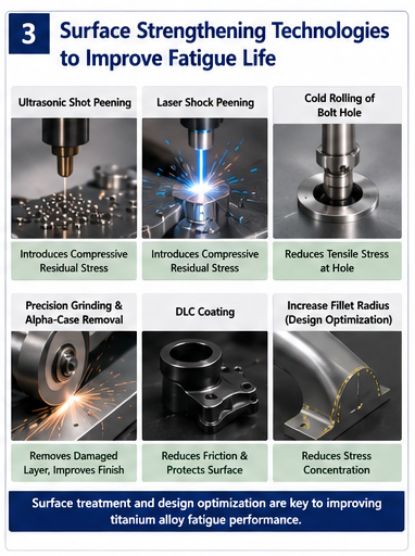
Fatigue performance can be improved through a combination of material processing, surface treatment, and structural optimization.
Shot Peening and Laser Shock Peening
Shot peening and laser shock peening introduce beneficial compressive residual stresses into the surface layer.
These compressive stresses can reduce the effective tensile driving force for fatigue crack initiation and early crack propagation.
Potential applications include:
Titanium alloy connecting rods
Aerospace shafts
Blades
Landing gear components
Fatigue-critical structural parts
Cold Rolling of Fastener Holes
Fastener holes are common fatigue-critical locations because they create significant local stress concentrations.
Cold expansion or hole cold rolling can modify the residual stress state around the hole and improve fatigue resistance.
Typical applications include:
Aerospace fastener holes
Titanium structural joints
High-load connection points
Precision Grinding and Surface Finishing
For high-performance titanium alloy components, final machining and surface finishing processes should control:
Surface roughness
Tool marks
Residual stress
Grinding damage
Surface contamination
Oxygen-enriched layers
Therefore, precision Titanium Alloy Machining requires more than simply achieving dimensional tolerances.
DLC Coatings
Diamond-like carbon (DLC) coatings can reduce friction and wear in selected sliding and contact applications.
Potential applications include:
Titanium alloy moving parts
Robot joints
Bushings
Marine components
Wear-critical interfaces
However, the fatigue benefit of a DLC coating depends on coating adhesion, thickness, substrate condition, contact loading, and service environment. It should therefore be validated for the specific application rather than assumed to improve fatigue life universally.
Structural Design Strategies for Improving Fatigue Life
Fatigue cracks frequently initiate at locations where stress concentration is high.
Designers should therefore minimize:
Sharp corners
Abrupt section changes
Deep narrow grooves
Sharp hole edges
Poorly designed thread roots
Uncontrolled machining marks
Increasing transition radii is one of the simplest methods for reducing local stress concentration.
A typical design strategy is:
Larger Fillet Radius → Lower Stress Concentration → Lower Local Fatigue Stress → Improved Fatigue Life
This approach is particularly useful for titanium alloy brackets, robotic joints, aerospace components, shafts, and other cyclically loaded structures.
Titanium Alloy Fatigue Advantages and Engineering Challenges
| Category | Performance Characteristics | Main Mechanism | Typical Applications / Failure Locations |
|---|---|---|---|
| Fatigue Advantages | High specific strength and good corrosion resistance | Appropriate microstructure delays crack initiation | Aerospace structures, vibration components |
| Surface Sensitivity | Machining marks and residual stress can reduce fatigue life | Surface defects become crack initiation sites | Titanium shafts, flanges |
| Hydrogen-Induced Damage | Hydrogen uptake may promote embrittlement under certain conditions | Hydrogen accumulation and hydride formation | Chemically processed components |
| Corrosion Fatigue | Aggressive environments can accelerate crack growth | Environmental interaction at the crack tip | Marine and chemical equipment |
| Fretting Fatigue | Small relative motion causes coupled wear and fatigue damage | Contact stress + wear + crack initiation | Blade dovetails, bolt holes |
| Anisotropy | Processing can produce directional fatigue properties | Microstructure and forging flow direction | Forgings and rolled bars |
| High-Temperature Fatigue | Fatigue properties vary with temperature and environment | Oxidation, creep, and microstructural changes | Elevated-temperature aerospace components |
Titanium Alloy Fatigue Design Workflow
A reliable fatigue assessment should follow a systematic engineering process.
Step 1: Identify the Material
Specify the exact alloy grade, such as:
Ti-6Al-4V / TC4
Ti-6Al-2Sn-4Zr-2Mo
Beta titanium alloys
Medical titanium alloys
Other application-specific titanium alloys
Step 2: Define the Microstructure
Determine whether the material has:
Equiaxed / Bimodal / Lamellar / Other microstructure
Step 3: Define the Loading Condition
Determine whether the component experiences:
High-cycle fatigue
Low-cycle fatigue
Very-high-cycle fatigue
Variable-amplitude fatigue
Thermal fatigue
Thermomechanical fatigue
Fretting fatigue
Step 4: Evaluate Surface Condition
Consider:
Machining → Surface Roughness → Residual Stress → Surface Defects → Surface Treatment
Step 5: Define the Service Environment
Identify whether the component operates in:
Air / Humid Environment / Seawater / Chloride Environment / Hydrogen Environment / High Temperature
Step 6: Select the Appropriate Fatigue Method
| Condition | Recommended Method |
| High-cycle fatigue without known cracks | S-N curve |
| Low-cycle fatigue | Manson-Coffin strain-life method |
| Variable-amplitude loading | S-N + Miner damage accumulation |
| Known cracks | Paris law / fracture mechanics |
| Damage-tolerant structures | Crack growth analysis |
| Fretting fatigue | Component testing + specialized modeling |
| Complex structures | FEA + fatigue testing |
Why titanium alloy machining Matters for Fatigue Performance
For a non-critical cosmetic component, dimensional accuracy and appearance may be the primary manufacturing requirements.
For aerospace, medical, robotics, and high-performance mechanical components, however, fatigue reliability depends on much more than dimensional accuracy.
The final fatigue performance of a titanium component is determined by the interaction of:
Material Grade
↓
Microstructure
↓
Heat Treatment
↓
Machining Process
↓
Surface Integrity
↓
Residual Stress
↓
Service Environment
↓
Loading Condition
↓
Fatigue Life
This is why CNC Machining Titanium alloy requires careful control of cutting parameters, tool condition, surface finish, heat generation, residual stress, and final finishing processes.
A TC4 component with optimized heat treatment, controlled machining, excellent surface integrity, and appropriate surface strengthening can perform very differently from a component with the same nominal alloy grade but significant machining damage.
Titanium alloys provide an excellent combination of specific strength, corrosion resistance, and fatigue performance, making them important materials for aerospace, medical, robotics, marine, and high-performance engineering applications.
However, titanium alloy fatigue strength and fatigue life are not determined by alloy grade alone.
The most important factors include:
Microstructure
Heat-treatment condition
Surface integrity
Residual stress
Machining quality
Environmental exposure
Fretting contact
Temperature
Loading conditions
Structural stress concentration
For high-reliability titanium components, engineers should select the appropriate fatigue methodology, including S-N analysis, Manson-Coffin strain-life analysis, Miner damage accumulation, or Paris-law crack-growth analysis.
Most importantly, laboratory material data should be adjusted or validated against the actual component's manufacturing condition and service environment.
For precision CNC Machining of titanium alloy parts, controlling surface integrity, minimizing stress concentrations, selecting appropriate heat treatment, and applying suitable surface strengthening processes can play a critical role in achieving reliable long-term fatigue performance.
Frequently Asked Questions
What factors affect titanium alloy fatigue life?
Titanium alloy fatigue life is affected by microstructure, surface roughness, machining marks, residual stress, heat treatment, stress ratio, loading frequency, environmental conditions, temperature, and fretting contact.
Is Ti-6Al-4V good for fatigue applications?
Yes. Ti-6Al-4V offers a strong combination of strength, corrosion resistance, toughness, and fatigue performance. However, its actual fatigue behavior depends strongly on microstructure, surface condition, heat treatment, and service environment.
How can titanium alloy fatigue life be improved?
Fatigue life can be improved through optimized microstructure and heat treatment, precision machining, improved surface integrity, compressive surface treatments such as shot peening or laser shock peening, hole cold expansion, optimized fillet radii, and appropriate protective coatings.
What is the best method for predicting titanium alloy fatigue life?
There is no single method suitable for every application. S-N curves are commonly used for high-cycle fatigue, Manson-Coffin methods for low-cycle fatigue, and Paris-law fracture mechanics for fatigue crack growth and damage-tolerance applications.
Why is surface finish important for titanium alloy fatigue?
Machining marks, roughness, tensile residual stress, and surface damage can act as fatigue crack initiation sites. Therefore, surface integrity is particularly important for fatigue-critical titanium alloy components.


