


| Comparison Dimension | Dual Swivel Head Type (A/B Axis) | Tilting Swivel Head Type | Dual Rotary Table Type (A/C Axis) | Tilting Worktable Type | One Swivel Head + One Rotary Table Type (C Axis + A/B Axis) |
|---|---|---|---|---|---|
| Core Technical Principle | Dual rotary axes are integrated into the spindle head, directly controlling tool orientation. The worktable only performs linear motion (X/Y/Z), no rotation/tilting. | One axis is a swivel head spindle, the other is a non-vertical rotary table (spindle axis not perpendicular to the table). Tool posture + workpiece positioning motion control. | Dual rotary axes are integrated into the worktable (A/C axes), directly controlling workpiece posture. The fixed spindle only performs linear motion; rotary axes are non-vertical with linear axes. | Dual rotary axes are integrated into the worktable (A/C axes). The rotary axis is not perpendicular to the spindle; the worktable performs tilting/rotation, while the spindle remains fixed vertically. | Dual rotary axes are split between tool & workpiece: 1. Tool axis controls tool posture (A/B); 2. Workpiece axis (C) controls rotation; 3. Linear axes move, spindle is non-vertical with the rotary table. |
| Core of Motion Control | 1. TCP point must be opened for real-time compensation of tool tip deviation caused by spindle rotation; 2. Tool path precision planning to avoid tool interference; 3. Three-axis smooth interpolation (NURBS / preview control) to suppress sudden acceleration changes. | 1. Non-vertical axis kinematics modeling, precise coordinate system switching; 2. Spindle + non-vertical rotary linkage optimization to optimize tool axis posture; 3. Non-orthogonal error compensation to eliminate geometric errors. | 1. Dual rotary table (A/C) coordinate calculation, adapting to non-vertical systems; 2. Workpiece coordinate and rotary table linkage to ensure machining trajectory; 3. Large load dynamic response control to avoid centrifugal vibration. | 1. Non-vertical worktable system kinematics compensation; 2. Tilting/rotation linkage with main spindle linear motion to control cutting posture; 3. Rigidity optimization under heavy load to reduce deformation. | 1. Tool axis (A/B) + worktable axis (C) synchronized R/GP compensation; 2. Non-vertical system comprehensive error compensation, double axis linkage; 3. Three-axis/worktable motion smooth interpolation to avoid vibration & layering. |
| Precision Control & Processing | 1. Spindle head bearing preload (P4 grade), controlling motion accuracy ±8″~±2″; 2. Full closed-loop linear grating ruler, repeated positioning accuracy ±0.002~0.004mm; 3. Real-time thermal deformation compensation to suppress spindle thermal errors. | 1. Non-vertical axis geometric error calibration (positioning accuracy ±0.005~0.01mm/3000mm); 2. Spindle + rotary table dual precision fitting to improve overall accuracy; 3. Low-speed smooth motion control to reduce cutting vibration. | 1. Dual rotary table bearings (YRT series) high-precision support, indexing accuracy ±2″~±5″; 2. Large-load worktable linkage optimization, controlling thermal deformation ≤0.003mm; 3. Non-vertical axis clearance compensation to eliminate backlash. | 1. Tilting worktable dynamic rigidity control to avoid cutting chatter; 2. Rotary axis and linear axis non-perpendicularity compensation to improve contour accuracy; 3. Plane/swing motion control, worktable flatness ≤0.005mm/3000mm. | 1. Dual-axis (tool + workpiece) independent precision calibration & comprehensive compensation; 2. Worktable (C axis) indexing ±1″~±3″, spindle (A/B) swing ±2″~±5″; 3. Non-vertical axis kinematics parameter calibration to ensure linkage accuracy. |
| Rigidity & Thermal Deformation Treatment | 1. Integrated casting for the spindle head + rib optimization to ensure initial rigidity; 2. Built-in cooling system (spindle/axis cooling), thermal deformation ≤0.01mm/°C; 3. Lightweight spindle head design to avoid excessive thermal inertia. | 1. Spindle + non-vertical rotary double-rib reinforcement design; 2. Non-vertical spindle uses heavy-duty bearings/guides to resist vibration; 3. Split structure thermal isolation to reduce heat conduction. | 1. Bed/table adopts double-walled honeycomb/rib design for high rigidity; 2. Dual rotary tables with large torque motors, heavy load ≥2000kg, thermal deformation ≤0.005mm; 3. Full enclosed protection (IP65) to prevent cutting fluid from affecting rigidity. | 1. Worktable integrated strengthening design, adapting to tilting/rotation conditions; 2. Non-vertical rotary axis uses large-diameter bearings to improve torsional rigidity; 3. Thermal deformation compensation for rotary tables/worktables to control temperature rise. | 1. Tool spindle lightweight + worktable side balance design; 2. Dual-axis independent cooling to control spindle/table temperature rise ≤1°C; 3. Non-vertical system inertia matching to avoid dynamic motion influence. |
| Process Matching & Technical Treatment | Application scenarios: ultra-precision curved surfaces, small parts, mold finishing (no spark erosion). Key treatment: 1. Tool axis/tip orientation correction, improving surface quality (Ra0.05~0.4μm); 2. 5-axis ultra-precision machining, optimizing tool path; 3. Small cut/high-speed cutting to ensure surface quality. | Application scenarios: complex curved surfaces, non-standard complex parts (special-shaped). Key treatment: 1. Non-vertical axis tool angle adjustment, deep cavity/undercut machining; 2. Low-vibration cutting strategy to maintain surface quality stability; 3. Low-speed high-torque cutting for difficult-to-cut materials. | Application scenarios: large structural parts, heavy-duty parts, aerospace structural key parts. Key treatment: 1. One-time clamping for large load cutting, reducing error sources; 2. Low-speed stable operation to avoid workpiece vibration; 3. Non-vertical system multi-face machining to improve efficiency. | Application scenarios: small/medium-sized complex parts, medical equipment, precision mold finishing. Key treatment: 1. Worktable tilt angle adjustment for inclined cutting/side cutting, completing 5-sided machining in one setup; 2. Tool anti-vibration treatment to reduce knife marks; 3. Dual rotary axis precision compensation to ensure contour deformation control. | Application scenarios: small/medium precision parts, molds, medical equipment, small and medium batch production. Key treatment: 1. Tool/worktable dual-axis linkage control, reducing clamping times; 2. Non-vertical system inclined surface machining to reduce errors; 3. Small parts high-precision finishing with surface roughness up to Ra0.1~0.8μm. |
| Typical Technical Difficulties & Solutions | Difficulties: Spindle head inertia causes motion shock; thermal deformation affects precision. Solutions: Lightweight spindle design, real-time thermal compensation, smooth interpolation control. | Difficulties: Non-vertical system kinematics is complex, with poor anti-interference capability. Solutions: Multi-axis linkage dynamic modeling, full closed-loop error compensation, non-orthogonal error compensation. | Difficulties: Large load dynamic response, dual rotary table error accumulation, heavy torque motor thermal error. Solutions: Dual-axis full closed-loop & grating ruler error compensation algorithm. | Difficulties: Worktable tilting causes rigidity drop; non-vertical thermal deformation is large. Solutions: Distributed error calibration, segmented thermal compensation, non-vertical linkage dynamic adjustment. | Difficulties: Tool/worktable dual-axis linkage precision is difficult to unify; non-vertical system errors are coupled with rotary errors. Solutions: Dual-axis independent calibration, double linkage error compensation algorithm, RTCP dual-point compensation. |
| Comparison Dimension | Dual Swivel Head (A/B Axis) | Tilting Swivel Head | Dual Rotary Table (A/C Axis) | Tilting Worktable (Swing Type) | One Swivel Head + One Rotary Table (C Axis + A/B Axis) | 3-Axis Machining |
|---|---|---|---|---|---|---|
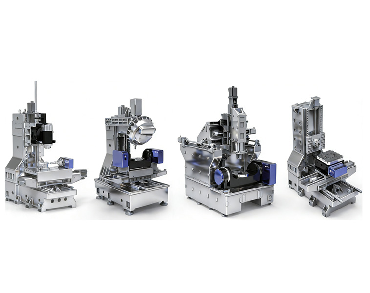
| Core Advantages & Features | Dual rotary axes integrated into the spindle head; direct control of tool posture. The worktable only performs linear motion, no tilting/rotation. Excellent tool axis flexibility, no shaking. Heat deformation has minimal impact on workpieces. | Non-vertical spindle + rotary table. Tool posture control is limited; the spindle head has high rigidity and chip removal. Non-vertical axes enable complex special-shaped machining. | Dual rotary axes integrated into the worktable; fixed spindle. High rigidity, large bearing capacity, small thermal deformation, high precision stability, suitable for heavy-load cutting. | Dual rotary axes integrated into the worktable; spindle is vertically fixed. Worktable tilting + rotation. One-time five-sided machining; excellent rigidity and chip removal, low deformation. | Swivel head (tool side) + rotary table (workpiece side) dual-axis rotation. Balances flexibility and stability; high rigidity and chip removal. Can achieve five-axis machining at a cost close to three-axis. | Simple structure, low operation threshold, easy to use. Low procurement/maintenance costs. Suitable for simple flat/hole processing; complex parts require multiple setups, low efficiency. |
| Clamping Times | 1 time (one-time completion of all processes, including multi-surface/curved surface/hole/undercut) | 1 time (non-vertical axes realize complex shapes; one-time completion of all processes) | 1 time (one-time clamping for multi-surface/lightening holes; no blind spots) | 1 time (one-time completion of five-sided/curved surface machining; no secondary clamping) | 1 time (one-time completion of multi-surface/curved surface machining; fewer clamping times) | 3-6 times (multi-surface/curved surface/hole machining requires multiple setups; large cumulative errors) |
| Surface Quality | Excellent (tool axis always aligned, no tool marks. Ra 0.05~0.4μm; mirror finish possible) | Excellent (non-vertical axes optimize tool path; continuous curved surfaces without steps. Ra 0.1~0.8μm) | Good (only spindle correction; poor surface fitting. Ra 0.4~1.6μm; manual polishing required) | Excellent (tool path optimized by tilting axis. Ra 0.2~0.8μm; minimal tool marks) | Good (tool axis aligned; surface quality close to five-axis. Ra 0.1~0.8μm) | Poor (vertical cutting generates feed lines/overcuts. Ra 1.6~6.3μm; requires large polishing) |
| Deep Cavity Machining Capability | Excellent (tool can enter at any angle; no dead angles for deep cavities/undercuts/closed structures) | Excellent (non-vertical head can enter from special angles; suitable for ultra-deep cavities/special-shaped deep cavities) | Medium (spindle fixed; deep cavity machining limited by tool length; prone to interference) | Medium-low (worktable tilting optimizes deep cavity cutting posture; reduces tool extension) | Good (can tilt at any angle; deep cavity undercut capability is better than dual rotary table) | Poor (cannot machine undercuts in vertical cutting; long extensions required for deep cavities; prone to tool shaking) |
| Rotational Machining Accuracy | Excellent (C-axis 360° rotation, roundness error ≤0.003mm; full closed-loop control) | Excellent (non-vertical axis system compensation, roundness error ≤0.005mm) | Good (worktable C-axis rotation, roundness error ≤0.002mm; rigid support) | Good (swing-type C-axis rotation, roundness error ≤0.003mm; small thermal deformation) | Good (workpiece C-axis rotation, roundness error ≤0.003mm; stable accuracy) | Poor (multiple clamping errors accumulate; roundness error ≤0.01mm, poor consistency) |
| Hole Machining Capability | Excellent (holes at any angle/deep holes/multi-holes completed in one clamping; position accuracy ±0.005mm) | Excellent (non-vertical spindle system adapts to angled holes at any angle; position accuracy ±0.005mm) | Good (multi-hole machining requires worktable rotation; position accuracy ±0.008mm, prone to hole position deviation) | Good (tilting worktable adapts to angled holes; position accuracy ±0.005mm, reduces hole position deviation) | Excellent (swivel head + rotary table movement; angled holes at any angle, position accuracy ±0.005mm) | Poor (multi-surface/angled holes require multiple clamping; position accuracy ±0.01mm, poor consistency) |
| Groove Machining Capability | Excellent (angled grooves/special-shaped grooves/deep grooves completed in one setup; no tool marks) | Excellent (non-vertical spindle system adapts to special-shaped/angled grooves; flexible machining) | Good (multi-surface grooving requires worktable rotation; deep grooves limited by tool length) | Good (tilting worktable optimizes grooving posture; reduces tool shaking) | Excellent (swivel head + rotary table movement; flexible grooving at any angle; no tool marks) | Poor (only vertical grooves can be processed; special-shaped/angled grooves cannot be machined; require multiple setups) |
| Undercut / Backdraft Machining Capability | Excellent (tool can enter at any angle; no dead angles for undercuts/closed structures; one-time forming) | Excellent (non-vertical head can enter from special angles; suitable for ultra-deep undercuts) | Poor (spindle fixed; undercut machining limited by tool length; prone to interference) | Medium (worktable tilting optimizes undercut posture; reduces tool extension) | Good (can tilt at any angle; undercut capability is better than dual rotary table/swing type) | Very Poor (undercuts cannot be machined in vertical cutting; requires disassembly/secondary clamping, no forming) |
| Tool Versatility Comparison | Compatible with all tool types: ball-end mills (curved surfaces), end mills (side cutting), drills (deep holes), special-shaped cutters. Can optimize tool posture to extend tool life by 30%+ | Compatible with all tool types, especially custom forming tools/long tools. Non-vertical posture reduces tool shaking and improves rigidity | Only compatible with conventional tools (end mills, drills). Deep cavity/undercut machining requires long tools; limited tool life | Compatible with conventional tools. Tilting posture optimizes cutting, reduces tool shaking and wear | Compatible with all tool types; balances flexibility and stability; extends tool life | Only compatible with conventional vertical cutting tools; cannot adapt to angled/special-shaped cutting; limited tool life |
| Machining Efficiency | High (reduced clamping/tool changes; complex curved surfaces formed in one pass. Efficiency 50%-80% higher than 3-axis) | High (non-vertical spindle system reduces auxiliary time. Efficiency 40%-70% higher than 3-axis) | Medium-high (fewer setups; large-volume roughing improves efficiency. Overall efficiency increased by 30%-50%) | Medium-high (fewer setups, reduced shaking. Efficiency increased by 30%-60%) | High (reduced clamping, surface quality and efficiency improved. Efficiency increased by 40%-70%) | Low (multiple setups/facing changes; long auxiliary time. Low efficiency for complex parts) |
| Machining Accuracy Comparison | Positioning accuracy ±0.005-0.01mm/300mm; repeat positioning accuracy ±0.002-0.004mm; A/C axis indexing accuracy ±3"-±8" | Positioning accuracy ±0.005-0.01mm/300mm; repeat positioning accuracy ±0.002-0.003mm; non-vertical axis system compensation indexing accuracy ±5"-±10" | Positioning accuracy ±0.005-0.01mm/300mm; repeat positioning accuracy ±0.002-0.003mm; A/C axis indexing accuracy ±2"-±5" | Positioning accuracy ±0.003-0.008mm/300mm; repeat positioning accuracy ±0.001-0.003mm; A/C axis indexing accuracy ±3"-±8" | Positioning accuracy ±0.005-0.01mm/300mm; repeat positioning accuracy ±0.002-0.004mm; A/C axis indexing accuracy ±2"-±5" | Positioning accuracy ±0.01-0.02mm/300mm; repeat positioning accuracy ±0.005-0.01mm; no rotation indexing accuracy |
| Surface Roughness (Ra) Comparison | Aluminum alloy: 0.05~0.2μm; mold steel: 0.1~0.4μm; titanium alloy: 0.4~0.8μm | Aluminum alloy: 0.1~0.4μm; mold steel: 0.2~0.8μm; titanium alloy: 0.4~1.6μm | Aluminum alloy: 0.4~1.6μm; mold steel: 0.4~1.6μm; titanium alloy: 0.8~3.2μm | Aluminum alloy: 0.2~0.8μm; mold steel: 0.2~0.8μm; titanium alloy: 0.4~1.6μm | Aluminum alloy: 0.1~0.4μm; mold steel: 0.1~0.8μm; titanium alloy: 0.4~1.6μm | Aluminum alloy: 1.6~6.3μm; mold steel: 1.6~6.3μm; titanium alloy: 3.2~12.5μm |
| Workpiece Load Capacity | Medium (≤500kg; limited by head bearings. Suitable for small/medium-sized parts) | Medium (≤800kg; head + rotary table combination. Load capacity higher than head-only) | Large (≤2000kg; worktable bearing. Suitable for large heavy-duty parts) | Medium-large (≤1500kg; swing-type worktable. Suitable for medium/large heavy-duty parts) | Medium (≤800kg; head + rotary table. Suitable for small/medium-sized parts) | Small (≤1000kg; worktable bearing. Suitable for all types of conventional parts) |
| Machine Load Characteristics | High load on the spindle head; light-weight design + cooling compensation. Linear axis load light; suitable for medium load cutting | Dual load on the head + rotary table; rigid balance design. Suitable for medium load cutting | High load on the rotary table; large torque motor + rigid support. Suitable for heavy load cutting | High load on the worktable; heavy-duty bearings + rigid structure. Suitable for medium/heavy load cutting | Dual load on the head + rotary table. Suitable for medium load precision cutting | High load on linear axes; suitable for large parts with heavy cutting, no rotation axis load |
| Procurement Cost (Domestic Reference) | High (Complex spindle head structure, direct/grating scale configuration. ~1.5-3 million RMB) | Medium-high (Custom non-vertical spindle system. ~1.2-2.5 million RMB) | High (High requirements for dual rotary tables, direct drive bearings. ~1.8-3.5 million RMB) | Medium (Swing-type structure. ~1.2-2.8 million RMB) | Medium (Best cost-performance ratio. ~0.8-2 million RMB) | Low (Simple structure. ~0.2-0.8 million RMB) |
| Maintenance Cost (Annual) | High (Spindle head bearings/encoders/cooling system maintenance. ~50,000-150,000 RMB/year) | Medium-high (Custom non-vertical spindle maintenance. ~40,000-120,000 RMB/year) | Medium (Rotary table bearings/seals maintenance. ~30,000-100,000 RMB/year) | Medium (Rotary table maintenance. ~30,000-100,000 RMB/year) | Medium (Head + rotary table maintenance. ~30,000-80,000 RMB/year) | Low (Only linear guide/screw maintenance. ~10,000-30,000 RMB/year) |
| Core Application Scenarios | Ultra-precision curved surfaces, mold cavities, aerospace blades, medical devices, semiconductor precision parts | Complex special-shaped parts, special deep cavities, custom precision parts | Large aerospace structural parts, heavy molds, automotive cover parts, large parts | Small/medium precision molds, medical devices, impellers, consumer electronics parts | Small/medium precision parts, general molds, medical devices, small-batch production | Ordinary parts, planes/simple contours, large-volume standardized parts |
| Machine Type | Aerospace | Mold Manufacturing | Medical Devices | Automotive / New Energy | General Precision / 3C | Energy / Heavy Industry |
|---|---|---|---|---|---|---|
| Dual Swivel Head | Excellent advantage: Suitable for large wings, fuselage frames, beams, blades; one-time clamping for deep cavities, undercuts and complex surfaces; flexible tool axis, no interference, high precision. | Excellent advantage: Automotive cover molds, precision injection molds, die-casting molds; high-gloss surfaces (Ra ≤ 0.4μm); deep cavities / undercuts with no dead angles, fewer tool marks. | Strong advantage: Artificial joints, bone plates, implants, precision instruments; small curved surfaces, high roundness, mirror surface finish, one-time forming. | Strong advantage: Complex housings, turbochargers, interior/exterior molds; multi-surface / angled holes / deep slots machined in one setup. | Fair: Small and medium-sized precision parts; high cost, limited load capacity. | Strong advantage: Large gas turbine components, heavy structures; large dimensions, complex internal cavities. |
| Tilting Swivel Head | Strong advantage: Special-shaped structural parts, special-angle blades, adapters; non-orthogonal axes adapt to special attitudes, excellent deep cavity accessibility. | Strong advantage: Special-shaped molds, multi-body inserts, complex cavities; special-angle cutting, avoids interference, continuous surfaces. | Strong advantage: Complex surgical instruments, non-standard implants; attitude flexibility, easy machining of microstructures. | Strong advantage: Complex steering knuckles, motor housings, new energy structural parts; multi-angle holes / slots completed in one setup. | Fair: Less versatile than “one head + one rotary table” configuration; high cost. | Strong advantage: Special-angle pipelines, special-shaped valve bodies; excellent adaptability for non-vertical attitudes. |
| Dual Rotary Table | Excellent advantage: Large structural parts, titanium / high-temperature alloy heavy-duty parts; high rigidity, large volume cutting, load capacity ≤ 2000kg. | Moderate advantage: Large molds, thick-plate molds, beams; high roughing efficiency, average finish quality. | Fair: Poor precision on small parts; limited suitability for large / deep cavities; suitable only for simple implants and instrument bases. | Strong advantage: Gearbox housings, base plates, large stamping dies; heavy-duty, multi-surface stable, high batch efficiency. | Fair: Limited flexibility on small parts; high cost. | Excellent advantage: Wind turbine gearboxes, large valve bodies, heavy-duty shaft parts; heavy load, high rigidity, stable cutting. |
| Tilting Worktable (Swing Type) | Excellent advantage: Engine blades, integral disks, small structural parts; 5-sided machining, high position accuracy, good chip removal. | Strong advantage: Small/medium precision molds, cavity inserts, electrodes; excellent surface quality, easy undercut machining, high stability. | Excellent advantage: Artificial joints, dental implants, minimally invasive instruments; ultra-high precision (≤0.003mm), bionic surfaces, clean machining. | Strong advantage: Turbocharger blades, ABS valve bodies, precision gears; multi-surface / angled holes / round profiles completed in one setup. | Strong advantage: Precision structural parts, connectors, housings; high precision on small/medium parts, good consistency. | Strong advantage: Small impellers, precision valves, instrument parts; high precision, complex curved surfaces. |
| One Swivel Head + One Rotary Table | Strong advantage: Medium-sized structural parts, blades, machine casings; balances flexibility, load capacity and versatility. | Excellent advantage: General molds, complex cavities, small/medium cover molds; cost-effective, good surface quality, full process completion in one setup. | Strong advantage: Surgical instruments, orthopedic implants, consumable molds; high precision, moderate cost, suitable for small/medium batches. | Excellent advantage: Motor housings, battery pack structures, complex brackets; multi-surface / angled holes / deep slots in one setup, efficiency improved by 30%+. | Excellent advantage: 3C mid-frames, precision assemblies, camera components; small/medium parts with complex structures, high efficiency and low cost. | Strong advantage: Medium-sized pumps/valves, construction machinery parts; high versatility, controllable cost. |
| 3-Axis | Disadvantage: Only simple structures, planes / holes; complex parts require multiple setups, poor precision, low efficiency. | Fair: Simple molds, templates, planar cavities; cannot machine complex curved surfaces / deep cavities / undercuts, requires polishing. | Disadvantage: Only single-axis bases and non-critical parts; fails to meet precision / surface quality / complex structure requirements. | Strong advantage: Simple brackets, cover plates, standard parts; high-volume, low-cost, easy programming. | Excellent advantage: Simple 3C parts, shells, standard parts; high volume, low cost, high efficiency. | Fair: Simple shafts, flanges, cover plates; cannot machine complex structures. |
China’s 5-axis CNC machining has evolved into a globally competitive solution with mature technology, stable equipment supply, and cost-effective delivery. It excels at complex surface machining, deep-cavity parts, and high-precision components for aerospace, automotive, semiconductor, and energy industries. With single-setup multi-face machining, it greatly reduces clamping errors, shortens production cycles, and improves surface quality. Supported by a complete industrial chain, China’s 5-axis machining delivers high precision, fast lead times, and reliable quality, making it the first choice for global customers seeking high-performance manufacturing solutions.
Huazheng specializes in high-precision 5-axis machining for complex, deep-cavity, and multi-surface components, with a maximum machining stroke of 1200×800×800mm. We match the right 5-axis configuration—dual swivel head, tilting head, dual rotary table, tilting table, or one-swing-one-turn—to your part geometry. Our capabilities ensure tight tolerances, excellent rotary accuracy, high material removal rates, and mirror-grade surface finishes. Backed by customized CNC surface treatment and strict process control, we reliably meet the demanding requirements of aerospace, new energy, semiconductor, and precision mold customers worldwide.
Equipped with 2 units, with a travel of 680 × 680 × 600 mm and a machining accuracy of up to 0.01 mm, suitable for high-complexity precision parts machining.
Equipped with 8 units, with a travel of 250 × 250 × 250 mm and a machining accuracy of up to 0.01 mm, ideal for high-precision machining of small and complex components.
Equipped with 6 units, with a travel of 800 × 600 × 550 mm and a machining accuracy of up to 0.01 mm, capable of meeting multi-face precision machining requirements.
Equipped with 6 units, with a travel of 500 × 400 × 300 mm and a machining accuracy of up to 0.01 mm, suitable for efficient machining of standard precision parts.
Equipped with 2 units, with a travel of 1500 × 600 × 350 mm and a machining accuracy of up to 0.02 mm, suitable for precision machining of large-sized workpieces.
Equipped with 10 units, with a travel of 700 × 400 × 400 mm and a machining accuracy of up to 0.02 mm, capable of supporting batch production of precision parts.
Equipped with 1 unit, with a travel of 1600 × 1400 × 800 mm and a machining accuracy of up to 0.02 mm, suitable for machining large workpieces and complex structural parts.
Equipped with 1 unit, with a working range of 600 × 600 × 400 mm and a processing accuracy of up to 0.01 mm, effectively improving surface finish and consistency of workpieces.
Equipped with 1 unit, with a measuring range of 600 × 800 × 600 mm and an inspection accuracy of up to 0.001 mm, capable of high-precision 3D dimensional inspection.
Equipped with 1 unit, with a measuring range of 400 × 300 × 200 mm and an inspection accuracy of up to 0.001 mm, suitable for precise profile and dimensional measurement.
Equipped with 1 unit, with a measuring range of 0–700 mm and an inspection accuracy of up to 0.001 mm, suitable for high-precision height and vertical dimension measurement.
Equipped with 1 unit, with a measuring range of 0.02–10 μm and a roughness accuracy of Ra 0.02 μm, capable of accurately evaluating surface quality.
Equipped with 1 unit, used for measuring coating thickness on product surfaces to ensure stable surface treatment quality.
Equipped with 1 unit, used for hardness testing of metallic materials to ensure compliance with material performance requirements.
Equipped with 1 unit, used for high-precision microhardness testing to meet material analysis requirements for precision parts.
Equipped with 3 units, with a measuring range of 0–200 mm and an inspection accuracy of up to 0.001 mm, suitable for rapid precision height measurement.
Equipped with 19 units, with a measuring range of 150–650 mm and an inspection accuracy of up to 0.005 mm, suitable for efficient daily dimensional inspection.
Equipped with 19 units, with a measuring range of 16–200 mm and an inspection accuracy of up to 0.005 mm, suitable for precise internal diameter measurement.
Equipped with 19 units, with a measuring range of 20–200 mm and an inspection accuracy of up to 0.005 mm, suitable for precise external diameter and thickness measurement.


